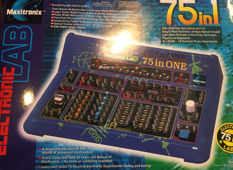
Today I worked on my first electronics project using the Maxitronix 75 in one electronics kit.


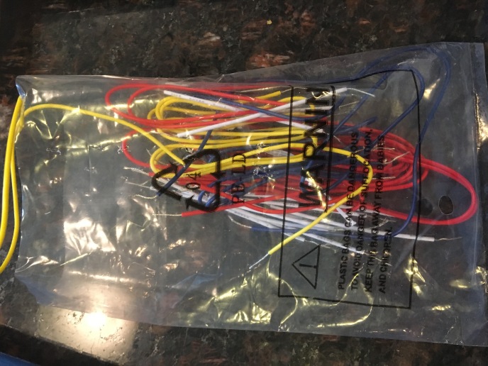
The kit comes with wires and an owners manual, and requires four double A batteries as pictured above.
In order to get a feel for the kit, I went through the first and second projects listed in the owner’s manual.
Basic Semi Conductor and Component Circuits
Project 1 focuses on the function of resistors in an electrical circuit. Resistors resist the flow of electricity in a circuit. Project 1a describes the function of a basic series of resistors, which is when two resistors are connected to each other and electricity flows from one resistor to the next in sequence.
Project 1a: Resistors in a series
The schematic in the manual directs the user to connect the electronic components in this order in order to demonstrate the function of a series of resistors.
3-5-109,6-108-42,1-40

The connection between 3 and 5 connects LED 1, to LED 2 with a short white wire.
The connection between 5 and 109 connects LED 2, to the key on the bottom right corner of the electronic lab with a long yellow wire.
The connection between 6 and 108 connects LED 2, to the left side of the key with a long yellow wire.
The connection between 108 and 42 connects the left side of the key, to the negative terminal of the battery located on the top right of the electronic lab with a medium sized red wire.
And finally the connection between 1 and 40 connects the left side of LED 1, to the positive terminal of the battery with a mid sized blue wire.
Once all the connections have been made, LED 1 illuminates, and upon pressing the key, LED 1 glows brighter.
This occurs because when the key is pressed it completes the circuit allowing electricity to flow through the key avoiding the lower resistor and flowing through only the higher resistor making LED 1 shine brighter. When the key is untouched the light is dimmed because the electricity faces resistance from the lower resistor and the higher resistor.
The brightening and dimming of LED 1 displays the role of a resistor in resisting the flow of electricity.
Project 1b: Resistors in Parallel
Parallel resistors are when two resistors are connected side by side allowing electricity to flow through both resistors at the same time.
The schematic in the manual directs the user to connect the electronic components in this order in order to demonstrate the function of parallel resistors.
2-5, 6-109, 3-108-42, 1-40

The connection between 2 and 5 connects LED 1, to LED 2 with a short white wire.
The connection between 6 and 109 connects the right side of LED 2, to the right side of the key with a long yellow wire.
The connection between 3 and 108 connects LED 1, to the left side of the key with a long yellow wire.
The connection between 108 and 42 connects the left side of the key, to the negative terminal of the battery with a medium length red wire.
And finally the connection between 1 and 40 connects the left side of LED 1, to the positive terminal of the battery with a medium length blue wire.
Once all of the connections have been made LED 1 illuminates. And upon pressing the key LED 1 glows brighter.
This occurs because when the key is pressed a second resistor is added to the circuit and due to the parallel connection, electricity flows through both resistors at the same time therefore resistance is decreased.
In this parallel connection, the total resistance is less than the lowest value resistor connected in parallel.
The brightening and dimming of LED 1 displays the role of parallel resistors in resisting the flow of electricity.
Final Thoughts
The first two projects of the kit were a great way to introduce me to the schematics of a circuit and the function of resistors in series and in parallel.
Now with this knowledge and skill set behind me I feel more comfortable moving on to more complicated projects with different outcomes.
Sources: Maxitronix Electronic Lab Owners Manual
